
Lorem ipsum dolor sit amet, consectetur adipiscing elit. Ut elit tellus, luctus nec ullamcorper mattis, pulvinar dapibus leo.Hydraulic transmission is used in a variety of mechanical equipment: machine tools, feeders, levelers, slitters, etc. The hydraulic transmission system of a machine tool is much more complicated than that of a jack.
Composition of the Hydraulic Transmission System
- Oil Tank
- Oil Filter
- Hydraulic Pump
- Relief Valve
- Throttle Valve
- Reversing Wind
- Handle
- Hydraulic Cylinder
- Worktable
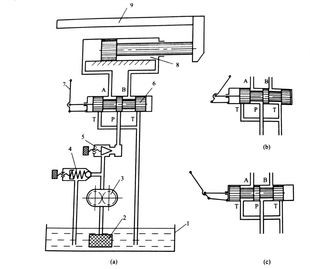
As shown in the figure is a simplified hydraulic transmission system of the machine tool reciprocating table. Through it, we can further understand the basic performance and composition of general hydraulic transmission systems.
In the figure, the hydraulic cylinder 8 is fixed on the bed, and the piston and the piston rod drive the workbench 9 to reciprocate.
The hydraulic pump 3 is driven by an electric motor (not shown in the figure), sucks oil from the oil tank 1 through the oil filter 2 and sends it into the closed system.
If the reversing valve handle 7 is pushed to the right so that the spool is in the position shown in the figure, the pressure oil from the hydraulic pump passes through the throttle valve 5 to the reversing valve 6 and enters the left cavity of the hydraulic cylinder 8, pushing the piston to work together Station 9 moves to the right.
The oil in the right chamber of the hydraulic cylinder 8 flows back to the oil tank 1 through the reversing valve 6 . If the reversing valve handle 7 is pulled to the left so that the spool is in the position shown in the figure, the pressure oil from the hydraulic pump passes through the throttle valve 5 to the reversing valve 6 and enters the right cavity of the hydraulic cylinder 8, pushing the piston to work together Station 9 moves to the left.
The oil in the left chamber of the hydraulic cylinder 8 flows back to the oil tank 1 through the reversing valve 6 . If the reversing valve spool is in the middle position shown in the figure, the two chambers of the hydraulic cylinder are closed and the piston stops.
The speed at which the table moves is regulated by a throttle valve 5 . When the valve port of the throttle valve increases, the flow of oil entering the hydraulic cylinder increases, and the moving speed of the worktable increases: when the throttle valve is closed, the moving speed of the worktable will decrease.
Turn the adjusting screw of the overflow valve 4 to adjust the preload of the spring. The greater the preload of the spring, the higher the oil pressure that can be obtained in the closed system, and the greater the maximum load that can be overcome when the worktable moves: the smaller the preload, the higher the maximum working pressure that can be obtained in the closed system The smaller it is, the smaller the maximum load it can overcome.
In addition, under normal circumstances, the amount of oil delivered to the system by the pump is more than the amount of oil required by the hydraulic cylinder, and the excess oil must be discharged back to the oil tank in time through the overflow valve. Therefore, the relief valve 4 plays the role of pressure regulation and relief in the hydraulic system.
Hydraulic Transmission System Consists of the Following Five Parts:
(1) Power component It is an energy conversion device that converts the mechanical energy input by the prime mover into liquid pressure energy. Its function is to provide pressure oil for the hydraulic transmission system, and the most common forms are various hydraulic pumps.
(2) The actuator is an energy conversion device that converts the pressure energy of the liquid into mechanical energy. Its function is to output force and speed (linear motion) or torque and speed (rotary motion) under the push of pressure oil. Such components include various types of hydraulic cylinders and hydraulic motors.
(3) Control elements
It is a component used to control or adjust the pressure, flow or direction of the oil in the hydraulic transmission system to ensure that the actuator completes the expected work. Such components mainly include various hydraulic valves, such as relief valves, throttle valves, and reversing valves.
(4) Auxiliary components refer to fuel tanks, accumulators, oil pipes, pipe joints, oil filters, pressure gauges, and flow meters. These components play the roles of heat dissipation and oil storage, energy storage, oil delivery, connection, filtration, pressure measurement and flow measurement respectively, so as to ensure the normal operation of the hydraulic transmission system and are an indispensable part of the hydraulic transmission system.
(5) Working medium
It plays a role in transmitting motion, power and signals in hydraulic transmission and control, including hydraulic oil or other synthetic fluids.
